

The Answer Depends on How You Apply It.
Tomato, tomahto. Potato, potahto. People refer to rotary valves as airlocks, airlock feeders and feeders. But are they really one in the same? No. That means rotary valves are misunderstood. Make no mistake, Magnum Systems builds rotary valves. It’s not until the rotary valve is applied into a pneumatic conveying system that it becomes either an airlock, airlock feeder or feeder. In other words, the rotary valve’s application in the system determines its name.
Here’s how a rotary valve can be applied into pneumatic conveying systems, thus determining what it becomes:
A rotary valve can be used as, and then becomes, a feeder.
A feeder meters product, and as it turns, material falls out and has a linear relationship of speed to volume. It’s as accurate as ±1 pocket of the valve. Other common types of feeders are:
A rotary valve can be used as, and then becomes, an airlock.
An airlock is a rotary valve that separates a pressure differential, keeping air either in or out. It’s usually found at the beginning of a pressure system or the end of a vacuum system. Other common types of airlocks are:
A rotary valve can be used as, and then becomes, an airlock feeder.
An airlock feeder simultaneously meters product in or out of a system and separates a pressure differential. It’s usually found at the beginning of a pressure system or at the end of a vacuum system. Common types of airlock feeders are:
A rotary valve is not the best metering device because it’s so small compared to the volume it can pass. Plus, it’s a horrible airlock because it’s manufactured with no sealing surfaces and only as small of a clearance between sealing surfaces as possible. A rotary valve leaks air. But it is the only device that can do meter product and separate a pressure differential at the same time.
Cast cylinders and endplates
Rotary valves have a cast cylinder and endplates. All housings and end plates of Magnum Systems rotary valves are cast from high quality gray iron. Some sizes are also available in stainless steel. Strong housing and end plates make for precision feeding and a long life. Castings allow the use of strengthening ribs in areas on the housing and end plates which would be difficult if not impossible if fabricated.
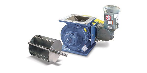
Rotors
Rotary valves have a welded steel rotor to meter material through the cylinder. Rotors, both open- and closed-end, are made integral by welding 3/8” thick vanes onto a pre-machined shaft. The closed-end rotor has a shroud welded on each end of the assembly. Rotor shafts have large diameters for minimum deflection under load. Using steel rather than cast iron for the rotors gives the rotors strength to handle the pressures of a pneumatic conveying system. The rotor can be coated to help product flow.
Between open- and closed-end rotors, open-end rotors are usually a vendor’s “most popular” because they are less expensive. Closed-end rotors are usually used with abrasive materials and in airlock or airlock feeder applications. They require some form of air purge to keep the area between the shroud and endplate clear of material.
Relieved tips
Relieved tips reduce vane width on the tips and sides (Type 1 rotors). Some materials, such as sugar and similar products, tend to build up on the inside surfaces of airlock feeders. Relieved vanes allow the rotor to keep the buildup of product scraped off. They also reduces noise with certain powder materials by not allowing compression between the rotor and the housing.
Outboard bearings
Outboard bearings allow smooth rotation of the rotor with minimal deflection. Bearings are outboard to the end plates and are kept clean and free from foreign matter by their own factory seals. Bearings are not exposed to product or heat from material. They are factory lubricated for the life of the bearings.
U-cups and rope packaging
U-cups and rope packaging create an air tight seal around the shaft. They prevent air and material from escaping from around the shaft. Magnum Systems has other packing materials are available upon request.
Chain and sprocket drive with guard
A chain and sprocket drive with guard provides constant power to the rotor with a wide range of RPMs. Physical speed limitation is between 6 and 30 RPM due to the limitations of sprocket sizes and chain guards. Magnum Systems’ motors and gear boxes are sized to match the torque and overhung load required for each size airlock. Rotor speeds are controlled by sprocket size to maximize the range of
rotor RPM.
All rotary valves are sized per their Code of Federal Regulations (CFR) and stated as “water full,” which is the generic starting point in sizing rotary valves.
Good rules of thumb based on how the rotary valve is applied are:
The “math” for rotary sizing is very simple. Convert your desired rate to Cubic Ft/Min. Either pick an RPM and see what valve size is close to that or pick a valve size and measure your RPM.
Fill efficiency is the result of the following:
Exceptions to the “rules of thumb” are:
Since the application determines what a rotary valve becomes, our team works with you to ensure your pneumatic conveying system has the right component based on the application and your operation’s needs. Contact us to discuss your needs.