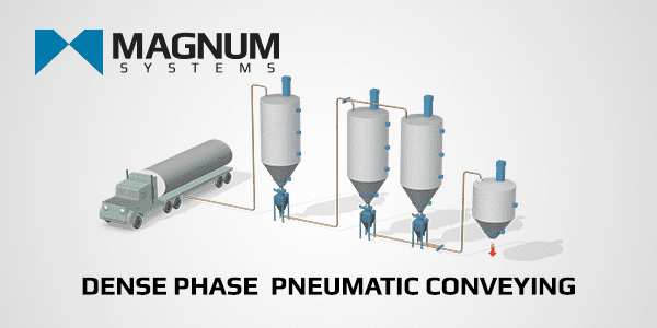

In dry materials handling, the product being conveyed and the application are used to determine the best type of conveying system. Highly abrasive products and those subject to degradation move best through a high-pressure, low-velocity conveying system. On long distance, high-rate applications, a high-pressure, low-velocity system can offer energy savings. Magnum Systems Dense Phase Pneumatic Conveying System is such a system. Unlike dilute phase systems, there is not an airlock feeder for introduction into the line. Dense phase systems use a pressure vessel or transmitter. While airlocks are normally limited to a pressure differential of only 15 psig, dense phase transmitters have no pressure limitation. With their high-pressure capability, dense phase systems allow for higher rates and lower velocities in the same line size. Slugs of product can be “pushed” through while dilute phase suspends all product in the air stream. Dense phase could be your best choice—particularly if you are dealing with abrasive products or products that degrade. Magnum Systems designs and manufactures both dense phase and dilute phase systems. We will help you select the best system for your application.
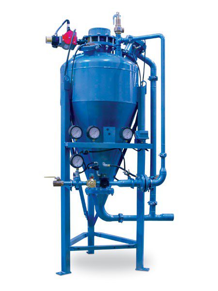

A key feature of a Magnum Systems dense phase conveying system is the exclusive air management system. By using a pressure control regulator, airflow control orifice and bypass valve, total air flow to the system and product-to-air ratio (the combination of air flow and conveying rate) are automatically controlled at the vessel.
When air flow and the product-to-air ratio are not accurately controlled, boosters or trace air lines are required. Not only are they expensive to purchase and install, but they add air to the system, increasing the energy requirements and line velocity. Our method saves money, allows easy access because all controls are located on the pot, and provides for an easier and more affordable installation.
Friction in a conveying line can only be overcome by pressure, not air flow. Air flow can increase or decrease friction, but pressure is the energy consumed to overcome the friction. The amount of pressure it takes to overcome friction is a function of product-to-air ratio, conveying line diameter, and conveying line length. Since line diameter and length are set, the only variable is product-to-air ratio. If the product-to-air ratio can be controlled, pressure can be controlled.
The key to unsurpassed system efficiency, reliability, flexibility, and overall performance is accurate control of air flow and product-to-air ratio at the vessel.
At Magnum Systems, we are so confident of the superiority of our air management system that we include air flow meters on all of our dense phase systems. These tell you exactly how much valuable compressed air is being consumed.
Magnum Systems is an American Welding Society and American Society of Mechanical Engineers qualified shop. All of our vessels are built to these standards. To assist with this, Magnum Systems has complete test facilities for both top and bottom discharge transmitters.
When handling a granular or non-fluidizable product, Magnum Systems recommends a bottom discharge transmitter. The principle of operation is the same, except that the bypass valve causes slug formations instead of steady state product-to-air ratio. When handling a fluidizable product, it is recommended to use a top discharge transmitter.
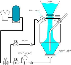

BYPASS VALVE OPERATION
The bypass valve is used to allow displaced air to vent from the top of the transmitter, through the bypass line, and down the convey line. This eliminates the need for
an additional piping connection for a vent line and valve. By using the convey line for venting, dusty air will be discharged to an existing dust collector.
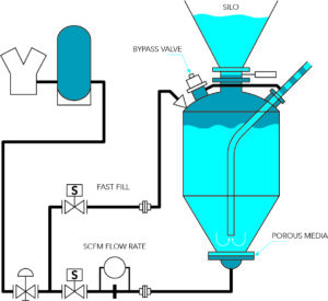

BYPASS VALVE OPERATION
The bypass valve remains closed to allow the transmitter to quickly come up to optimum operating pressure.
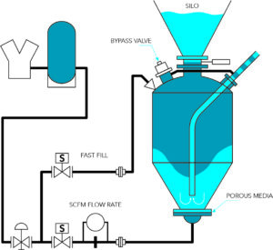

BYPASS VALVE OPERATION
The bypass valve accurately controls the product-to-air ratio as product is discharged from the transmitter. When the convey pressure is reached, the bypass valve bleeds clean air from the top of the vessel into the convey line. This brings the product-to-air ratio to the proper proportion for the selected convey pressure. This requires only a simple regulator setting on the bypass valve for field adjustment. The valve setting is initially determined based on product conveying characteristics and system configuration (i.e., line size, number of elbows, distance, etc.).
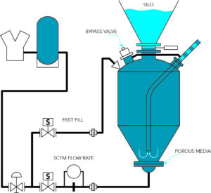

Bypass Valve Operation
The bypass valve remains closed as pressure decays below the normal operating pressure. Remaining air in the vessel is vented down the convey line eliminating the need for a vent line, vent valve and discharge valve. Valve controls are reset to allow for the next fill cycle.
Rail Car Unloading and In-Plant Transfer System
Dense phase conveying from rail car unloading pit to storage silos. In plant transfer from silos to receiving bins using a common convey line and patented slide diverter valve.
Ingredient Batch Weighing System
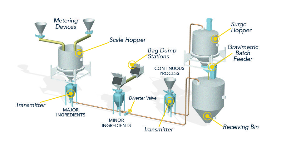

Major and minor ingredients are batch weighed and transported to a receiving bin or blending location. All products can be accurately metered, weighed and transported individually or as a complete batch. Also, transfer from customer continuous process.
Dust Collection Transfer System
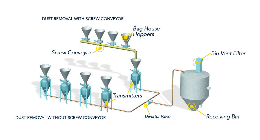

Collection of abrasive dust from a bag house or precipitator can be done one of two ways. A collection screw can direct product to a single surge hopper and transmitter and convey line can be used at each hopper outlet.
About Magnum Systems
At Magnum Systems, we take a total system approach, which allows us to look at your complete process and develop the most efficient engineered solution for your production line. Depending your material type, application environment, business objectives and financial goals, Magnum Systems designs a material handling solution that best fits your needs.
Have Questions? We've Got Answers!
Related Post
Mastering Integration in Manufacturing with Magnum Systems: A Deep Dive Podcast Episode
The Secrets of Valve Bag Sealing: Expert Insights from Magnum Systems
Maximizing Efficiency in Production Lines: The Role of Rotary Airlock Valves
Addressing the Complexities of Valve Bag Sealing with Wayne Revell